Experiment on Bipolar Junction Transistors
tutorial·@baa.steemit·
0.000 HBDExperiment on Bipolar Junction Transistors
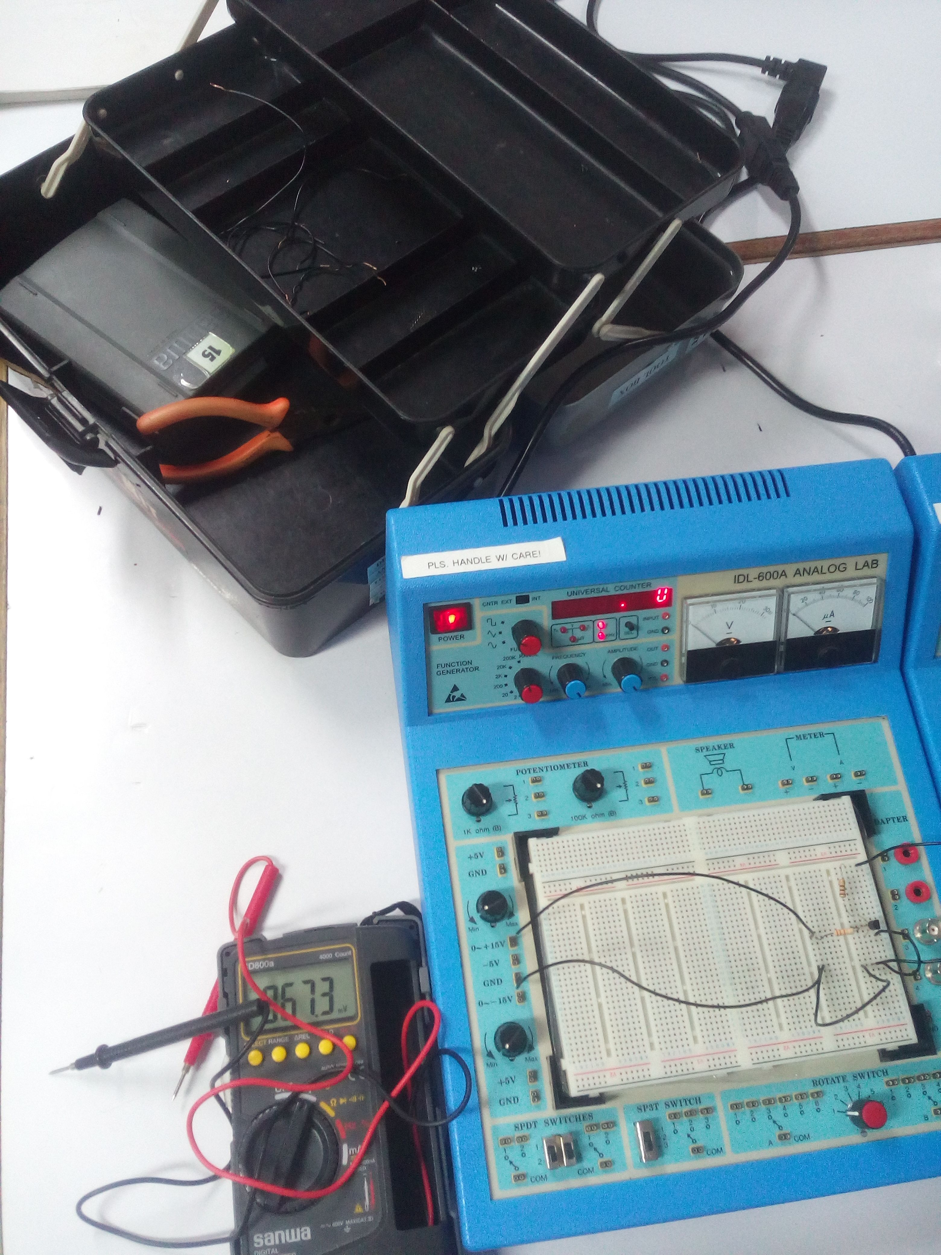 In our electronics subject, we had an experiment about bipolar junction transistors which was led by our instructor @engrdrdarwin. Our objective for doing this experiment is to measure and graph the collector characteristic curves for a bipolar transistor and to use the characteristic curves to determine the β(dc) of the transistor at a given point. <h2><b>Materials that we used:</b></h2> 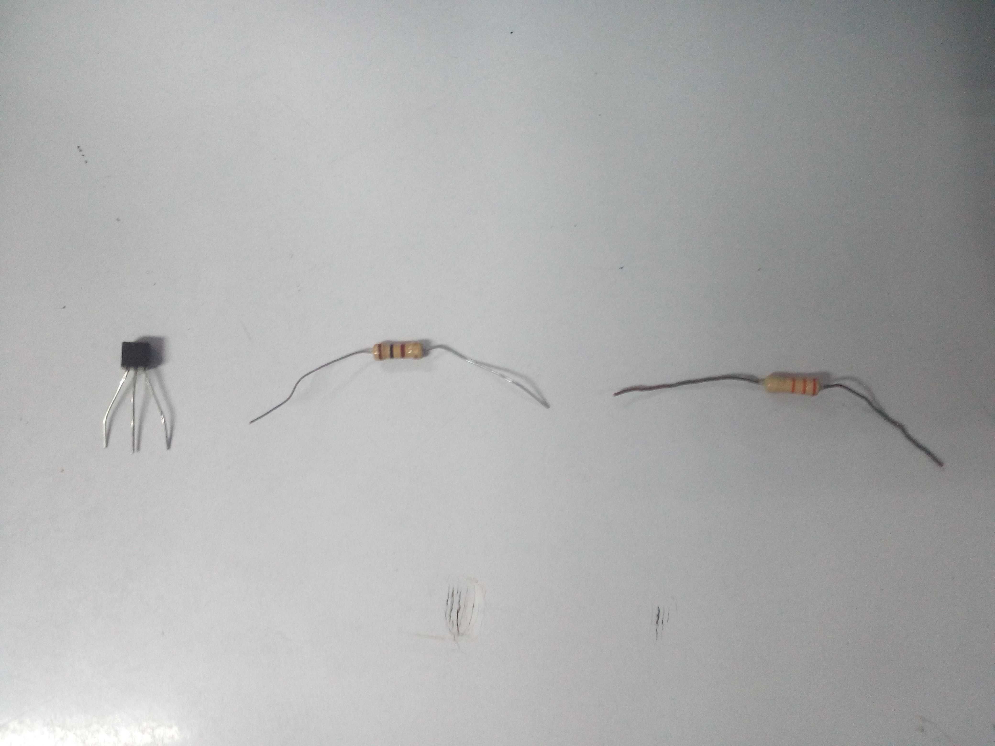 <center>Resistor: 100 Ω; 33 KΩ and Transistor: 2N3904 NPN or equivalent</center> 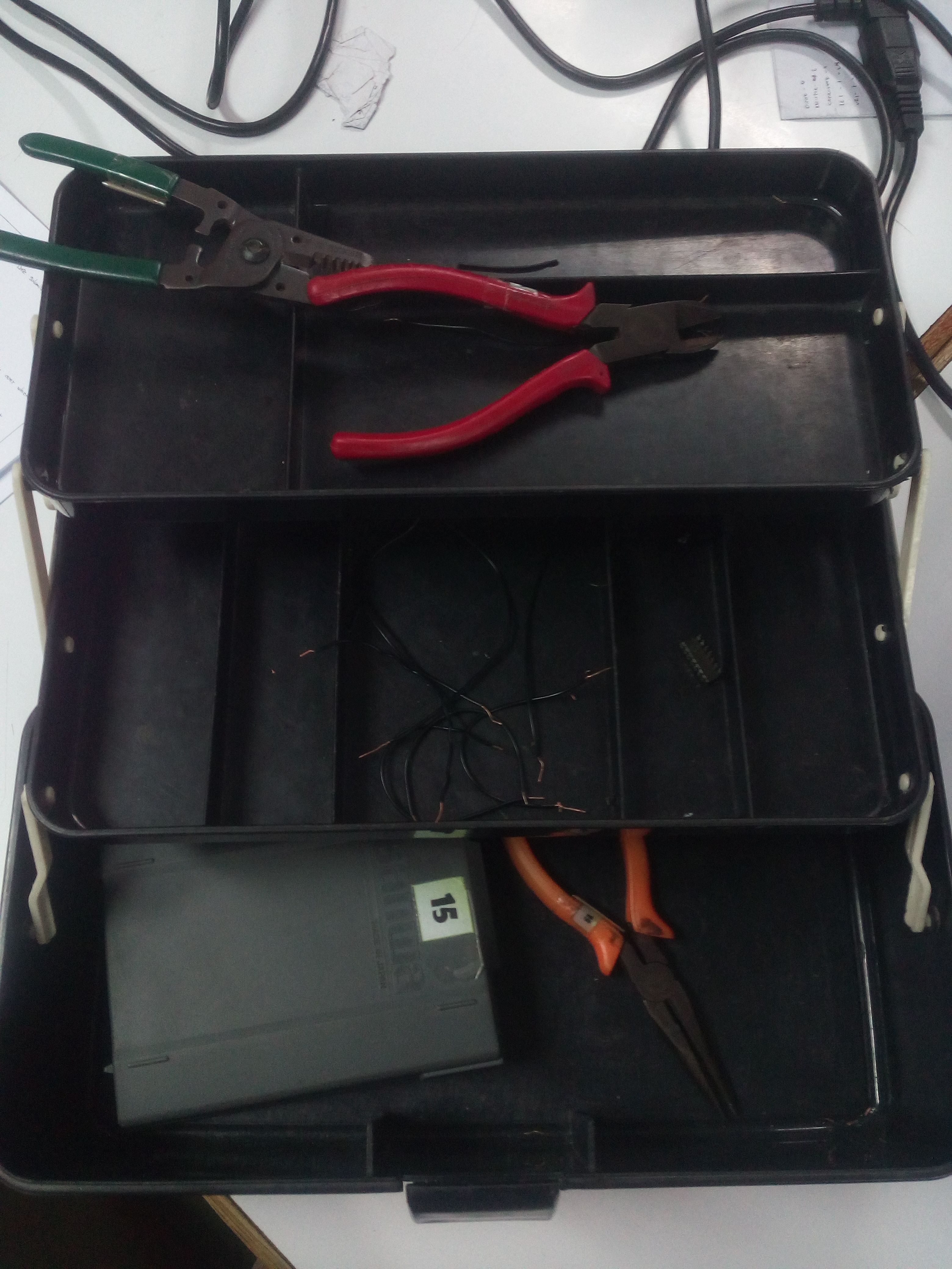 <center> Wire Cutters,Connecting Wires and Multitester </center> 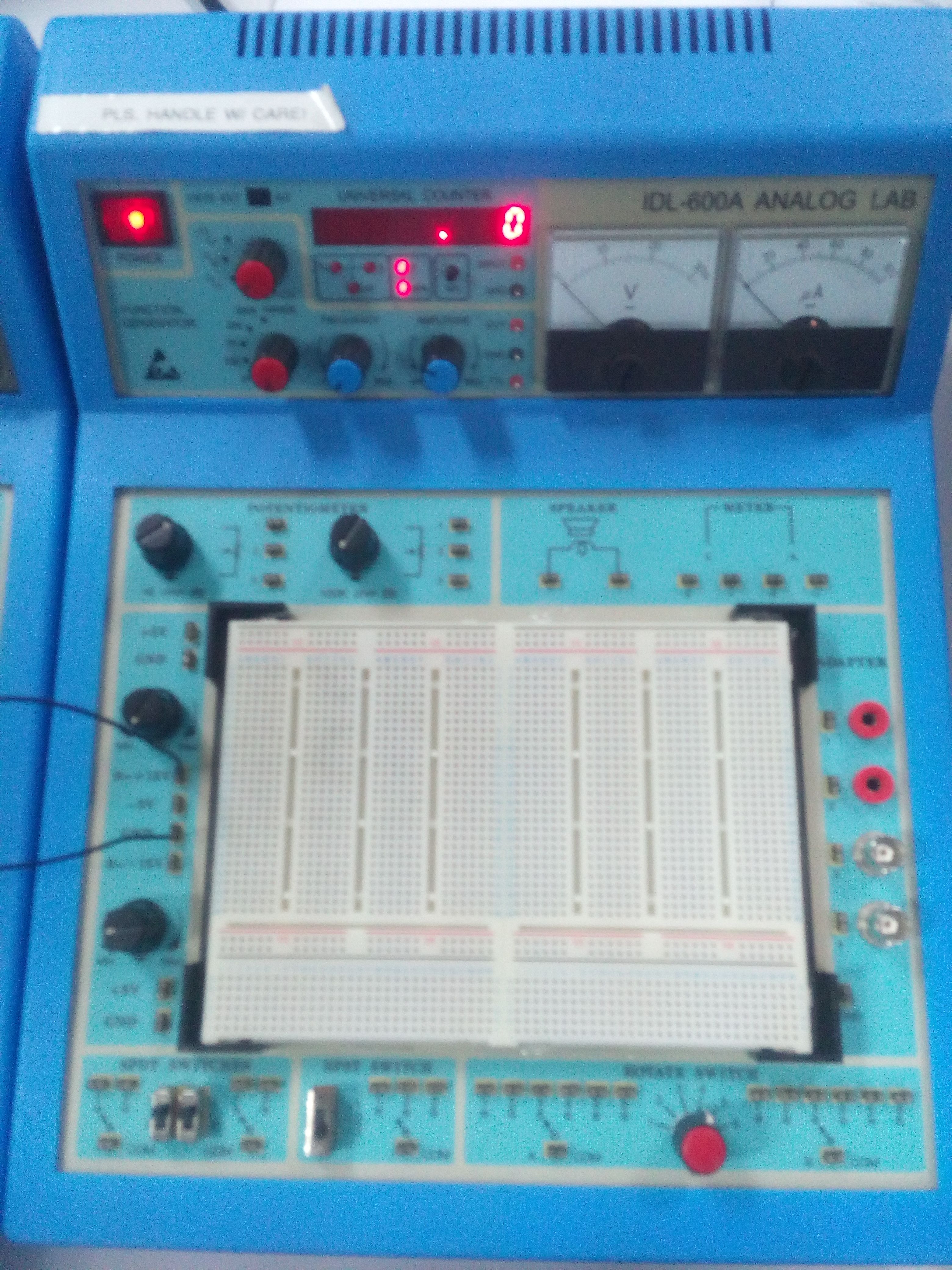 <center> Analog Trainer </center> <h2><b>Procedure:</b></h2> First thing that we did was to get the measured values of the resistors. Next was to construct this circuit to the breadboard on the analog trainer.  As you can see we will need 2 voltage sources for this experiment, since our analog trainer only contained one, we used another one to be the other source of voltage. 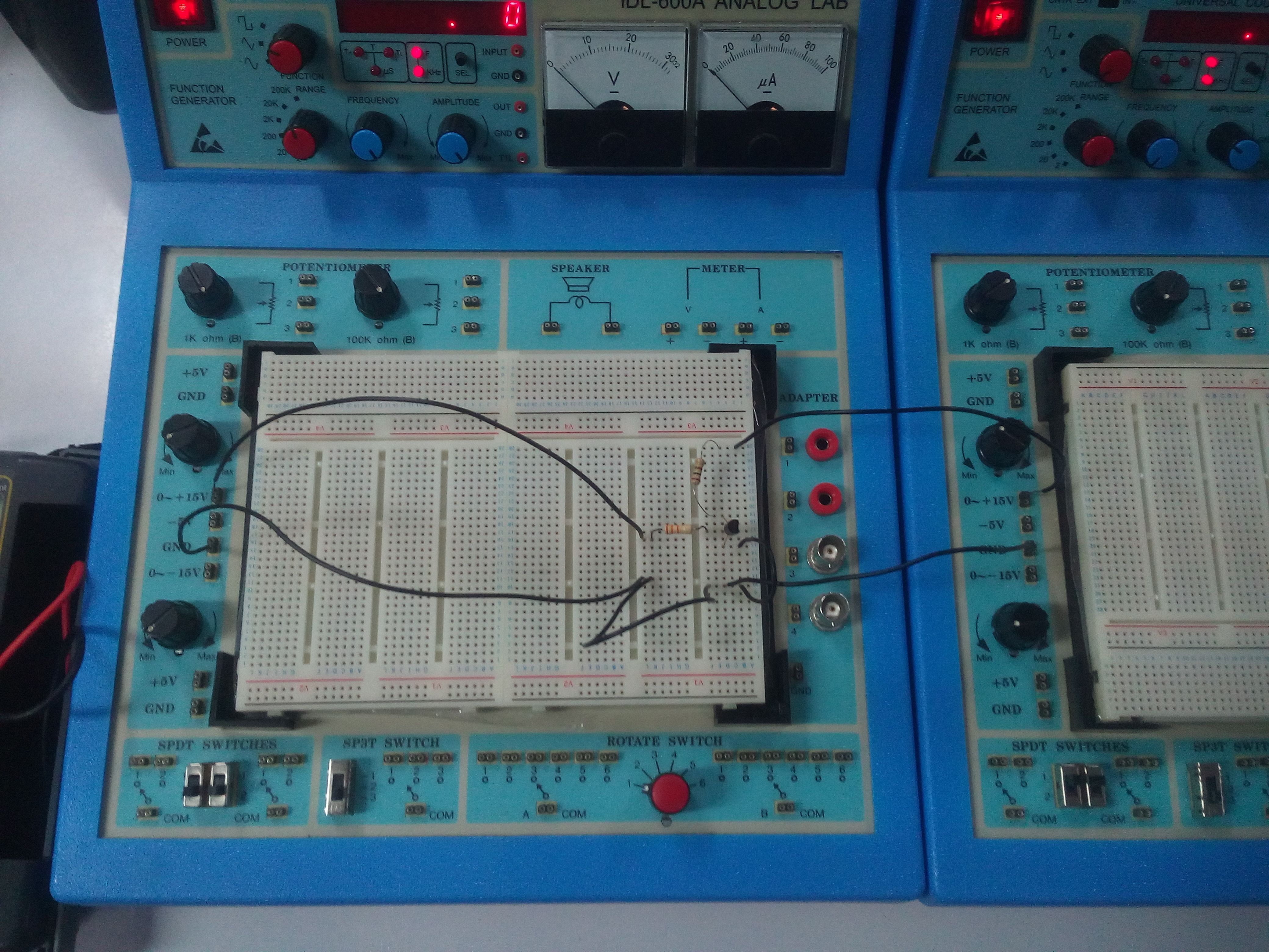 As we had finished constructing the circuit shown above, next we did was to get the voltage output on the resistor with 33 kilo ohms by adjusting the V(bb) till it achieves an output of 1.65 V, this sets up a base current of 50 nano amperes. After that we will need to get the V(ce) which should equal to 2.0 V by slowly adjusting the V(cc). Measure the voltage output in R2 which is the 100 ohms. 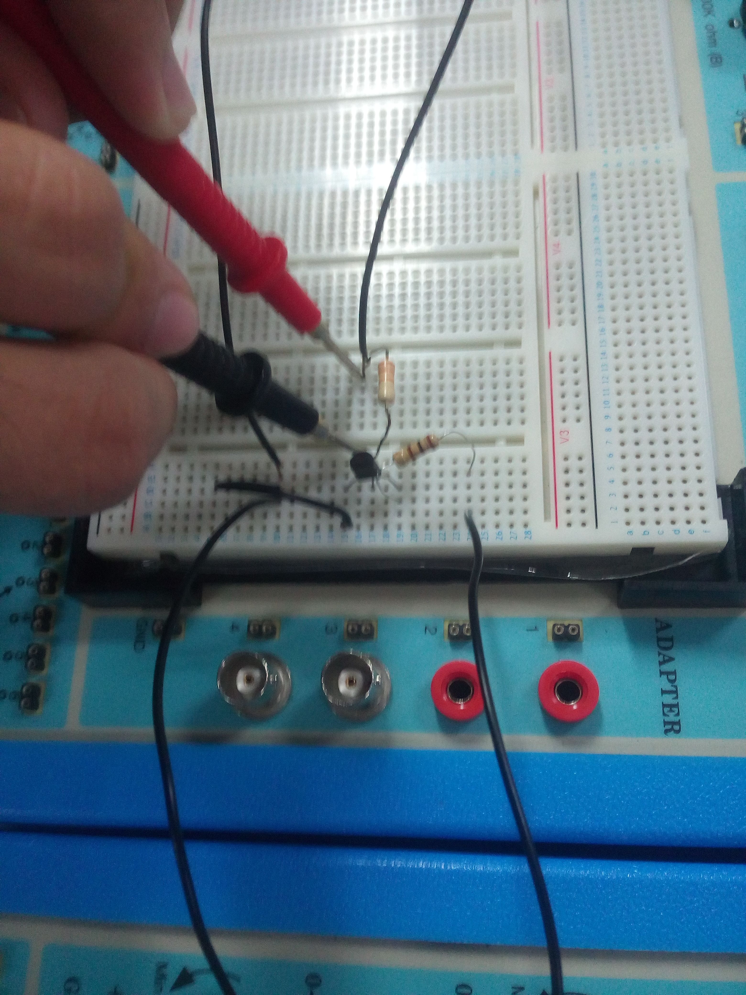<center>(Measuring output voltage on R1 = 33KΩ)</center> Maintain the V(bb) then adjust your V(ce) to obtain the required measured values on the table. From that you will be doing the same for the base current of 100 nano amperes just take note that, to obtain a base current of 100 nano amperes you will be required to have an output voltage of 3.3 V and for the 150 nano amperes you will be required to have an output voltage of 4.95 V. 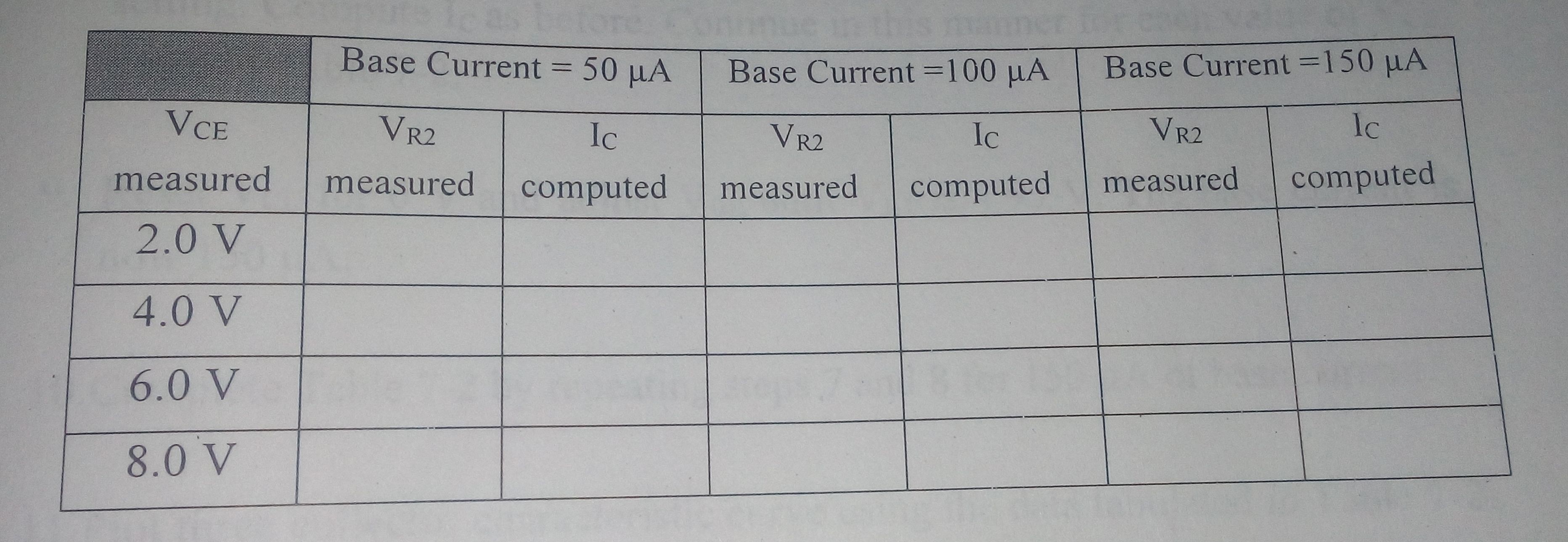 After completing the table above you will have to compute the current I(c) using the formula: <h2><center>I(c)=V(r2)(measured)/R2(measured)</center></h2> 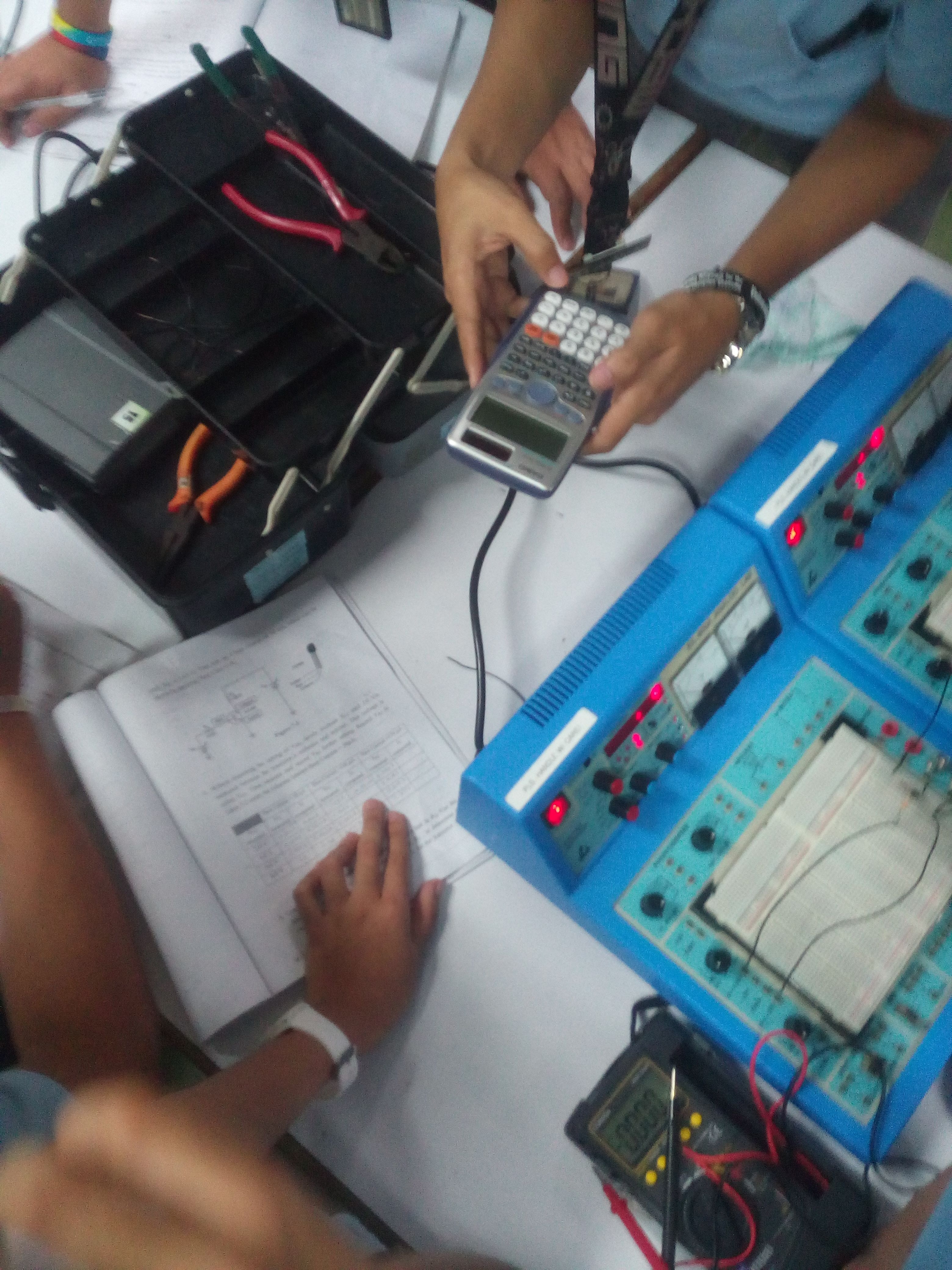 <center>(Computing the values for the current on the collector)</center> So that was it, I hoped you learned something from this post. There will be more to come so support me and follow my blog.  Yours truly, @baa.steemit
👍 baa.steemit, ejnavares, reyboot586, keybordjp, aiyeecanoy, broadcast, symonp, leofordking, inarix03, fivestargroup, primetimesports, finkployd, steemph.cebu, japh, leryam12, rafael.espina, bellatravelph, queenjventurer, smaeunabs, juecoree, glennamayjumaoas, namranna, jassennessaj, agentzero, tedzwhistle, jacoblayan, themanualbot, itinerantph, jamiz, caratzky, rfece143, jaderpogi, pizzanniza, jenesa, charmaingomez07, aribalcristian, saintjames, booster, legendarryll, wandergirl, purpleshangz, marysent, thinkingmind, speedvoter, resteemable, jenel, jonny-clearwater, darthnava, upmyvote, ali2star, qweku, duncankrista12, minnowsupport, pheonike, edrivegom, stephen.king989, jhermanbeans, pomperipossa, qwasert, myday, gamerveda, steemprentice, numpypython, decibel, cryptohustler, buildawhale, omargalk, thetravelingsa, thonnavares, ron.encila, ipumba, diezeldiddy, jvff, annedyosa, daisydelta, eetsmarielle, jefz,