Plasma Thruster!
science·@hellfire-labs·
0.000 HBDPlasma Thruster!
In this article I will be detailing one of the coolest experiments I have done thus far with my vacuum system. Through some very simple observations of plasma, I was able to create a mini thruster which directs plasma and electrons out of its nozzle just like a rocket engine! Being an Aerospace engineering student, it was only a matter of time before I built my own plasma thruster! As usual, I will explain the science behind its operation as best as I can and will provide some further reading below! 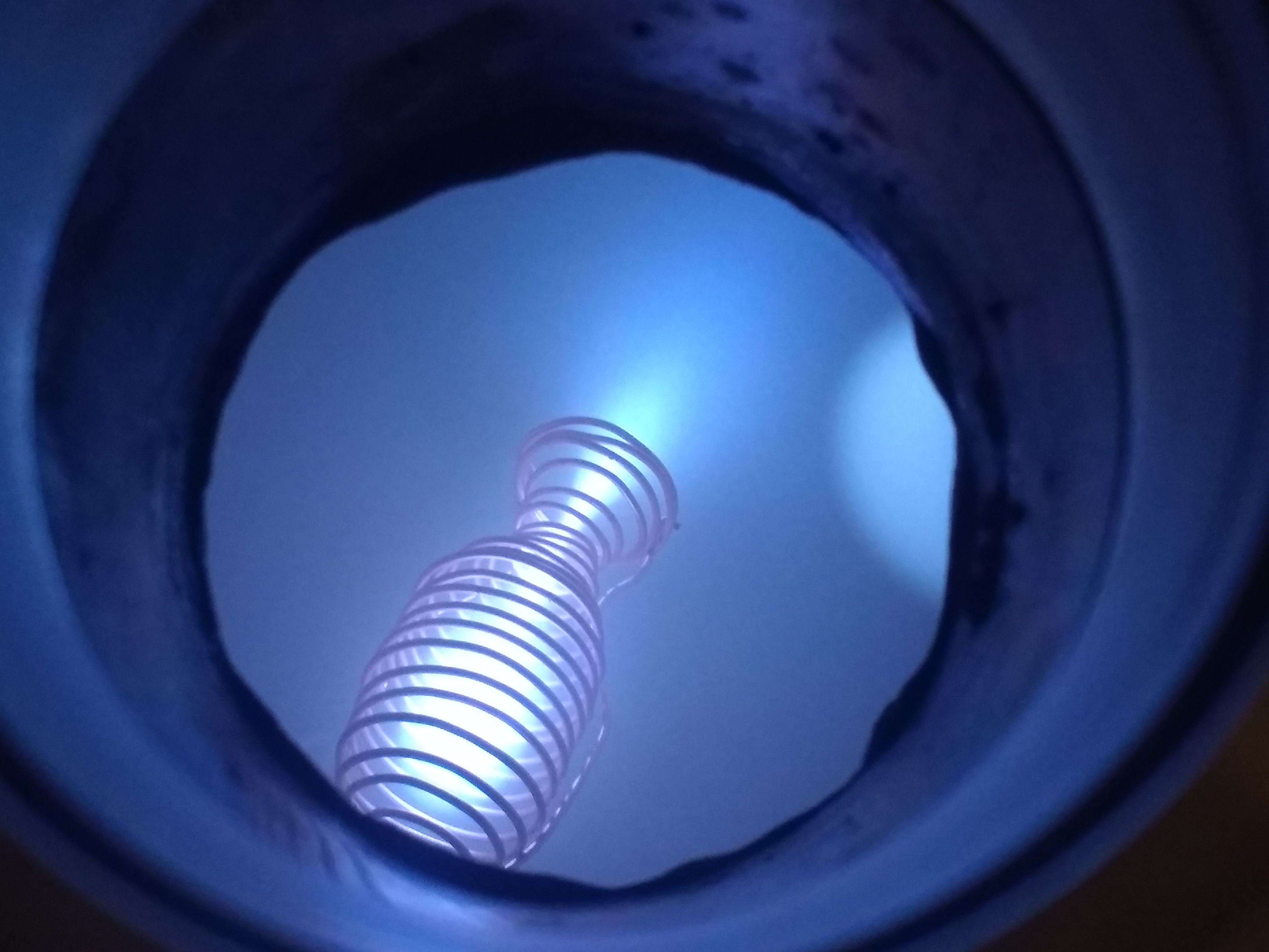 *Figure 1. Plasma blasts out of the nozzle on the engine* **How a rocket engine works** Before I dive into how this electron thruster operates, it would be beneficial to go over how a conventional chemical rocket works. For this purpose, I am going to borrow a diagram from NASA since they do a bit of dabbling in rocket science! 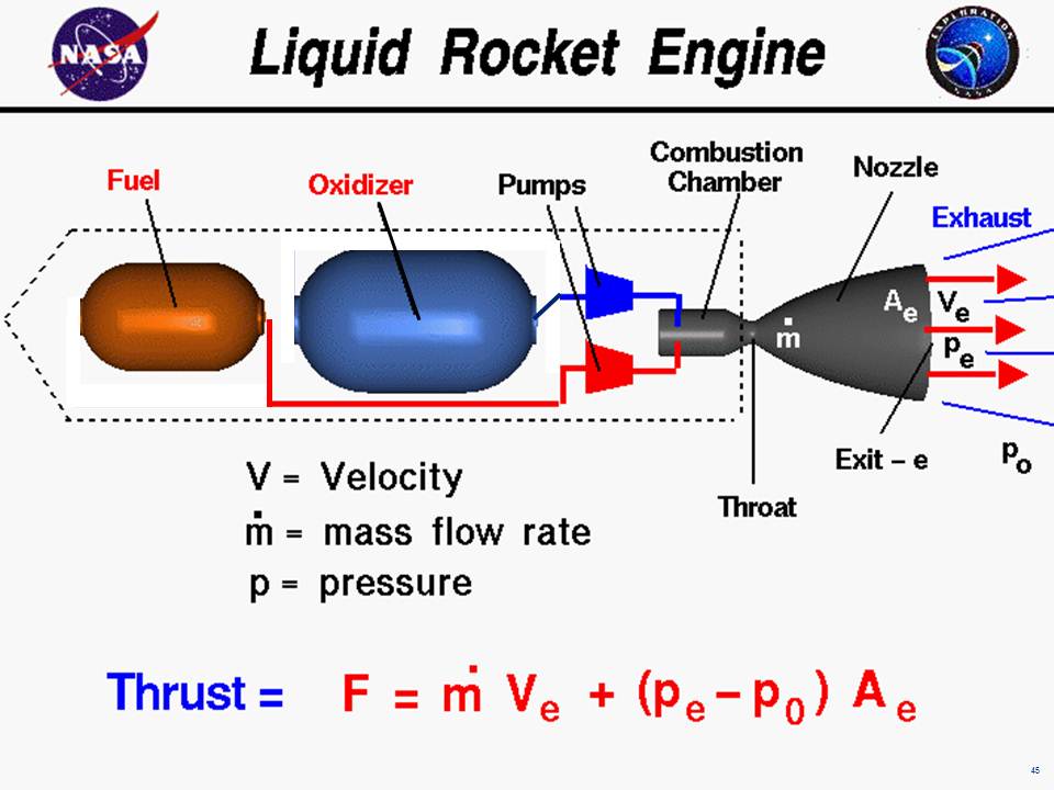 *Figure 2. Basic diagram of a liquid fueled rocket engine. (Image from NASA)* An engine works by extracting the chemical energy within a fuel and oxidizer mix and converting that into thrust. The fuel and oxidizer are mixed within the combustion chamber where they are ignited and burn releasing tremendous amounts of energy. This thermal energy is then converted into kinetic energy through the use of a de Laval nozzle. The operation of a rocket nozzle is very complicated and if you would like more information please use the Further Reading section below. This kinetic energy is then transferred to the vehicle which causes it to accelerate. This is how basic rockets work! **Plasma Thruster 1.0** 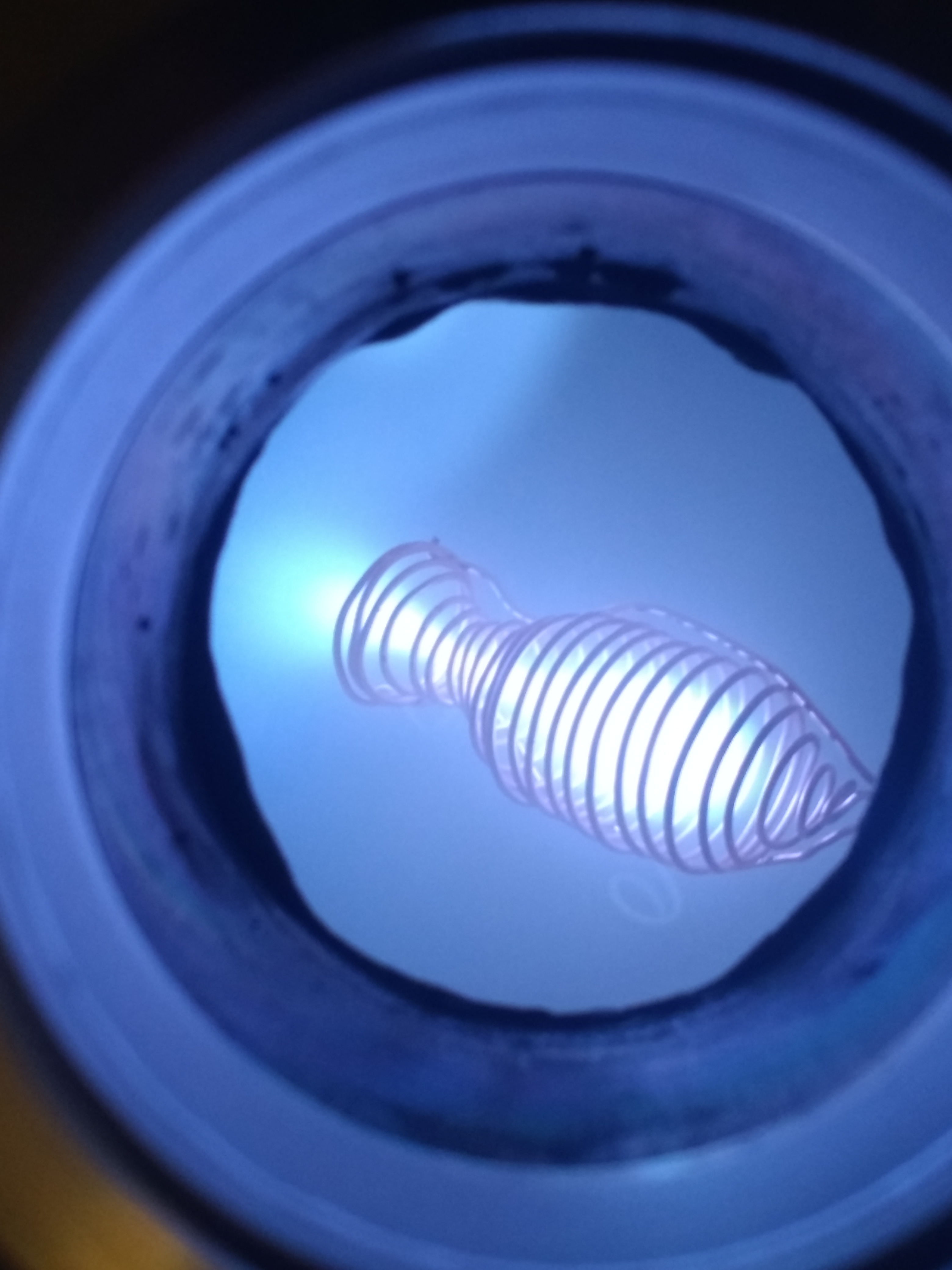 *Figure 3. Dense bright plasma within the main chamber is clearly visible.* The engine that I built operates substantially differently but maintains a few core similarities. For starters, there is still a "fuel" and there is a source of heat. The engine also generates thrust by shooting mass out of a nozzle! Of course, the same laws of physics and thermodynamics apply. Now before you get excited about blasting off into space with your brand new plasma rocket-pack, I have to dash your dreams with science. Unfortunately, the thrust generated by this method, and other plasma thrusters, is incredibly small. The record, according to Wikipedia, is currently around 5 Newtons of thrust in a lab environment! The reason they are still used is they are extremely efficient which can be read in more detail in the Further Reading section. I am unable to measure the thrust of my engine with the equipment I have, but it is so small it probably less than .001 Newton. The propellant that I used for this thruster is simply residual gas left inside of the vacuum chamber. This residual gas drifts about the interior of the vacuum chamber and eventually some of it ends up drifting into the engine body. Since the gas molecules are neutral, they are not attracted or repulsed by the strong electric field surrounding the chamber body(further explained below) allowing them to drift into the cloud of swirling electrons in the center of the engine. These gas molecules are then struck by electrons, turning them into ions which creates the bright plasma. Some of these newly formed ions get carried with the electrons out of the engine body while some collide with the wire and become neutral again. In this sense, the fuel is reusable as long as it drifts back into the engine at some later point in time. The only true input into this system is energy in the form of electric potential and current. Electrons are emitted from the negatively charged engine body and some become trapped within, forming the electron cloud. An additional bonus is that any positive ions that form outside of the engine will be attracted to the negative potential engine, and thus increase the concentration of free gas to be used as fuel near the engine! Now you may look at my plasma thruster and think "Well there are no walls! How can it hold back the plasma?!". The answer is through a virtual wall, or electric field. The spiral shape that encases the plasma is actually copper wire which is connected to a negative high voltage terminal. This high voltage generates a large negative electric field around the wire coil which repulses other negative charges, such as electrons. This allows you to confine negative electric charges! To help illustrate this point, I am going to use a diagram from one of my previous articles. 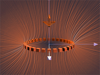 *Figure 4. The orange lines represent electric field lines and the more there are in a given area, the stronger the field. Note the dark spot within the ring structure* Extrapolating from the Figure 4, we can gather that there will be a low electric field in the center of a coil that is electrically charged. What this does is creates a strong electric field around an area of low electric field which is exactly what you want for containing a plasma! Once charged particles are created near the electric field, they are repulsed into the lower field region in the center of the structure. This occurs until enough particles accumulate that the charge in the center is comparable to the charge containing the particles. By this point, a dense ball of plasma has formed due to the large number of electrons bouncing around. Once they reach this equilibrium point, they look for a weak point in the field to escape. Think of squeezing a half-full water bottle with a tiny hole in the lid. As you squeeze, water fills up the air pockets until it entirely fills the bottle. At this point, the pressure is equalized and if you squeeze anymore, water will shoot out the top. This is very similar to how the Plasma Thruster 1.0 works. Figure 5. displays this plasma plume leaking out of an unintended point due to a bent wire and thus a weak point in the electric field. 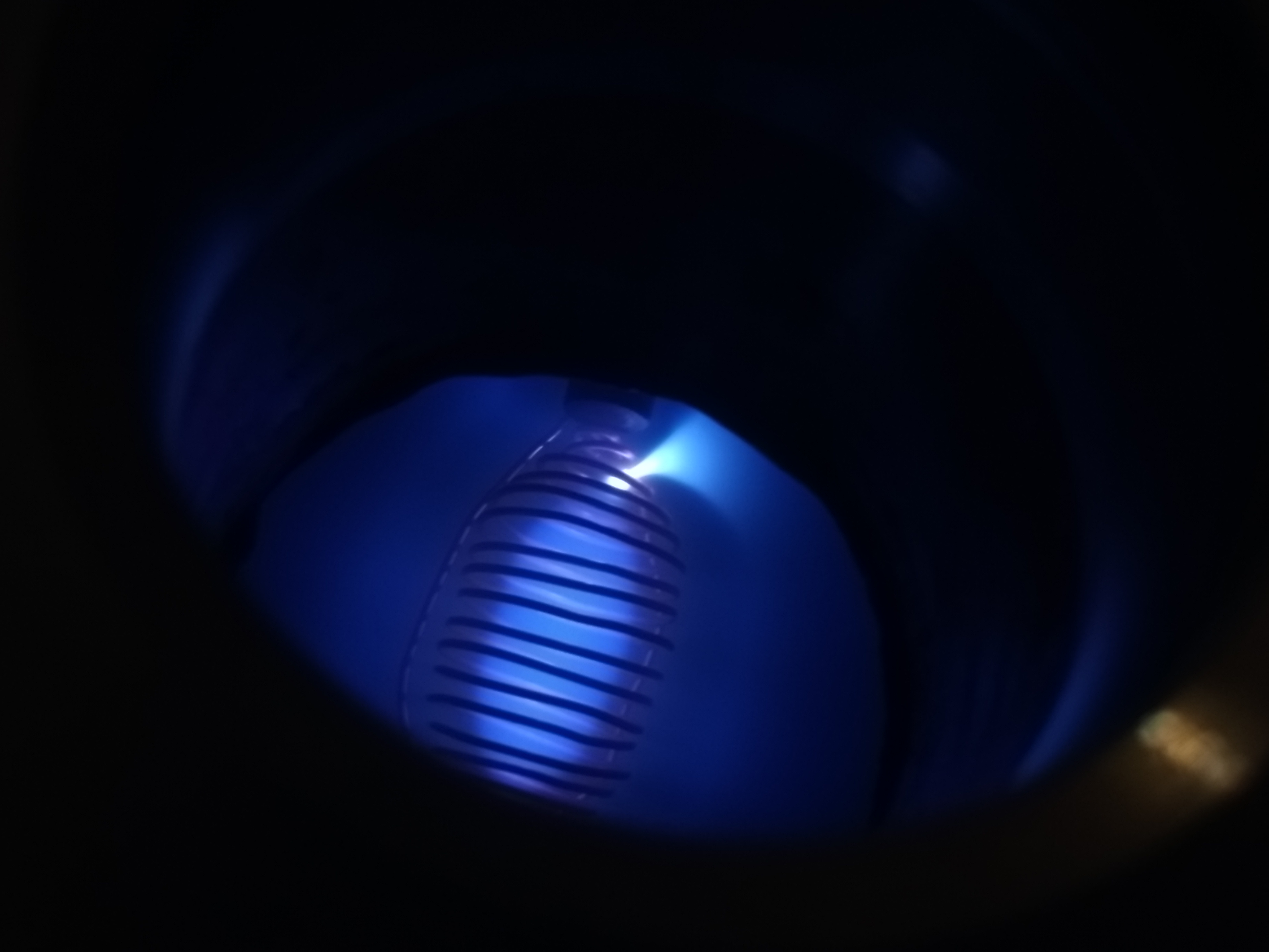 *Figure 5. Plasma leaking out the side of the thruster body* I showed many of these images in my previous article and an idea came to mind when I was reviewing them. If you artificially make the weak point, you can choose where you shoot the plasma and direct it! This lead to the current design of the plasma thruster. Adding a nozzle keeps the plume directed out and away from main body. There isn't too much to the design other than a little bit of wire wrapping, the physics takes care of itself! Hopefully this was a sufficient explanation of how the Plasma Thruster 1.0 works! **More Images!** 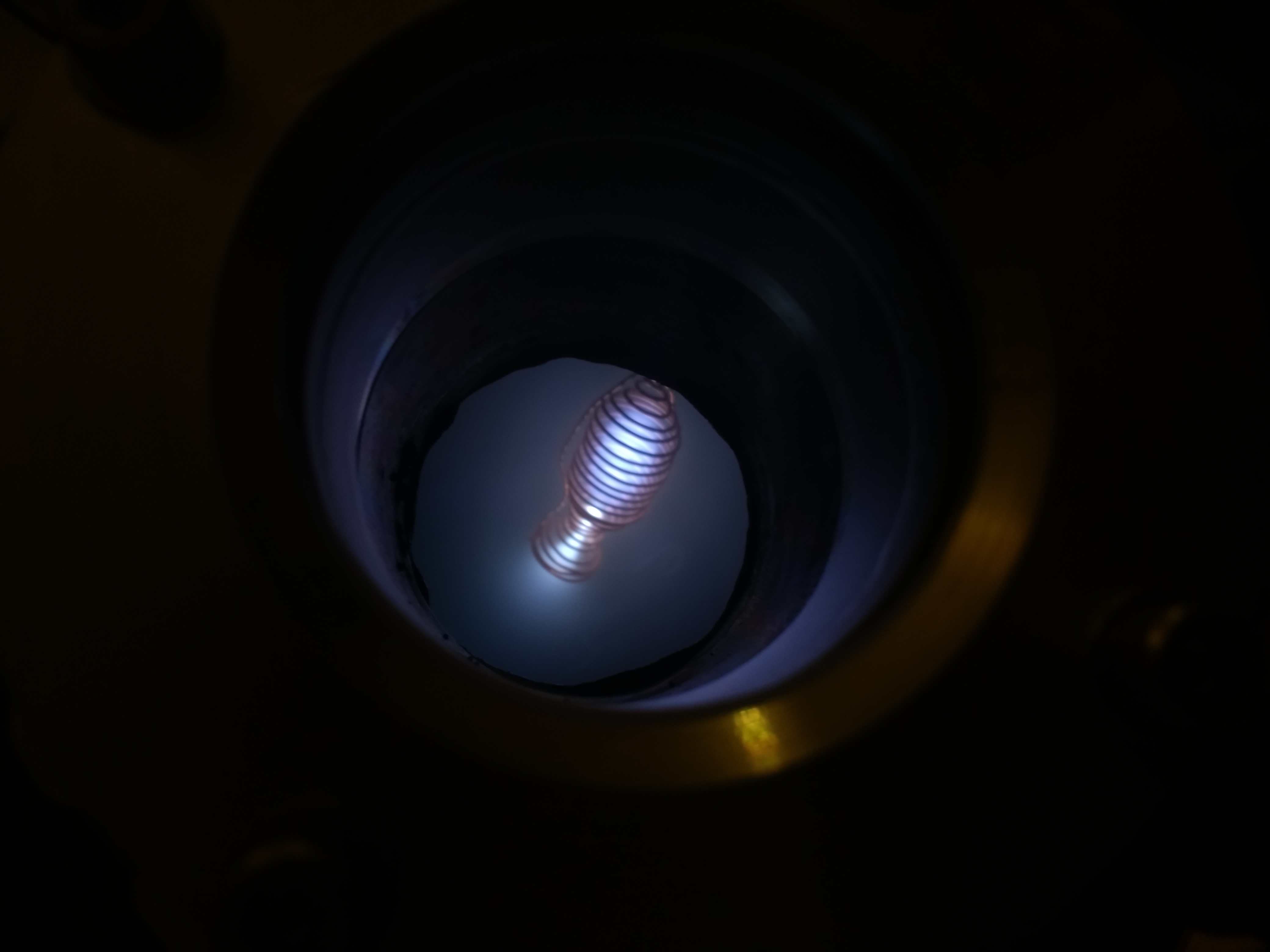 *Figure 6. Electrons are accelerated through the nozzle which creates a denser and hotter plasma in the throat(white area)* 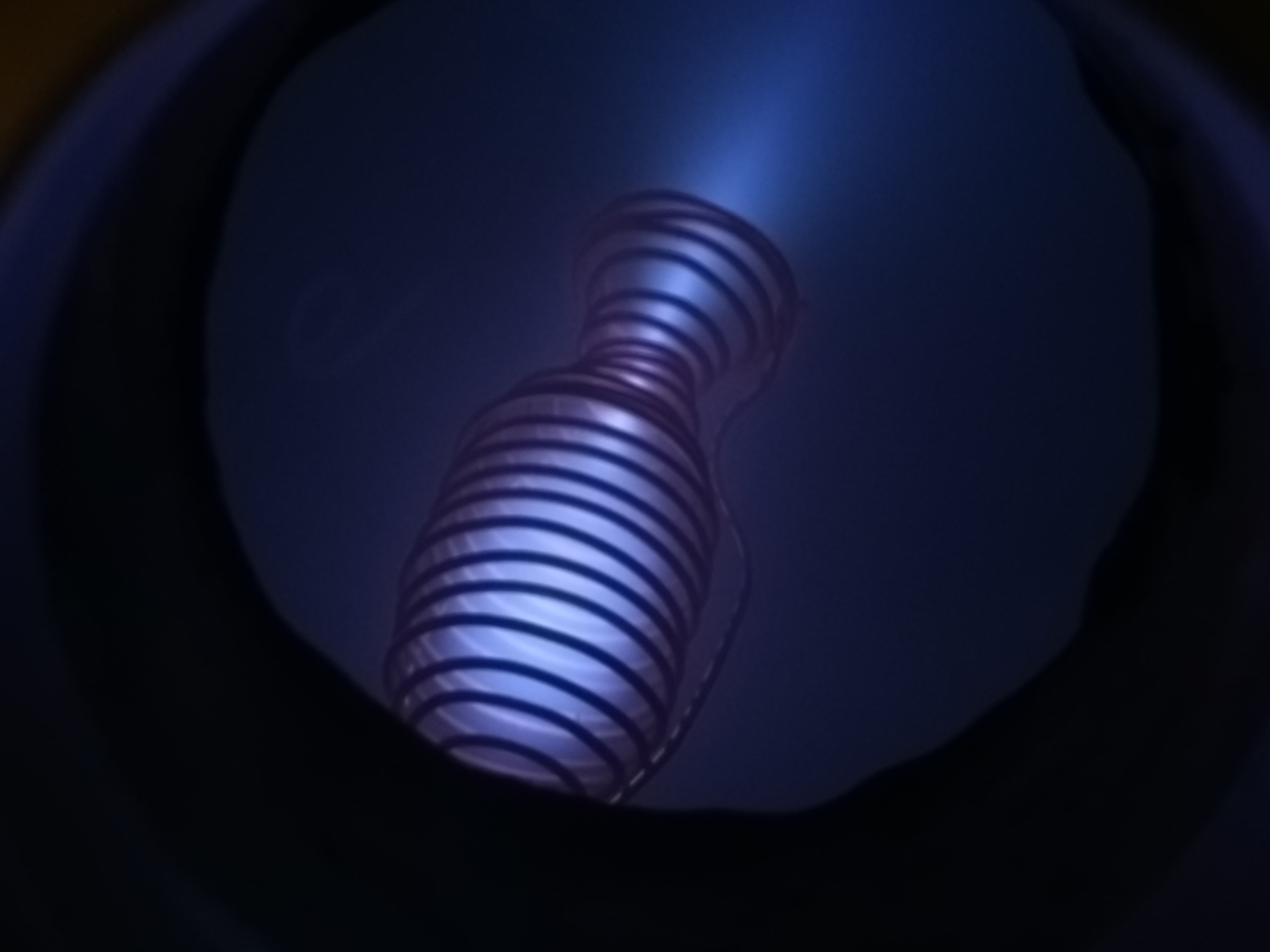 *Figure 7. A lower vacuum chamber pressure pushed the flow towards molecular conditions* 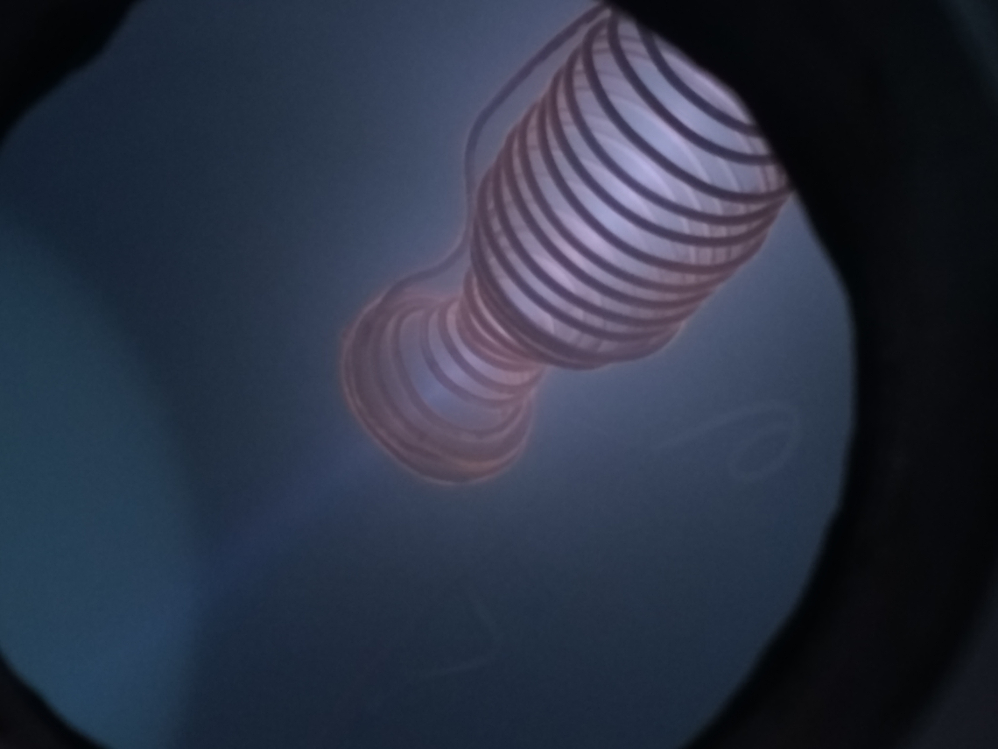 *Figure 8. Beam of electrons blasting out from the nozzle due to molecular flow conditions. Note the orange glow coming from the surface of the copper.* *Note regarding the orange glow* I am not sure what the cause of this is yet and will continue to investigate it! 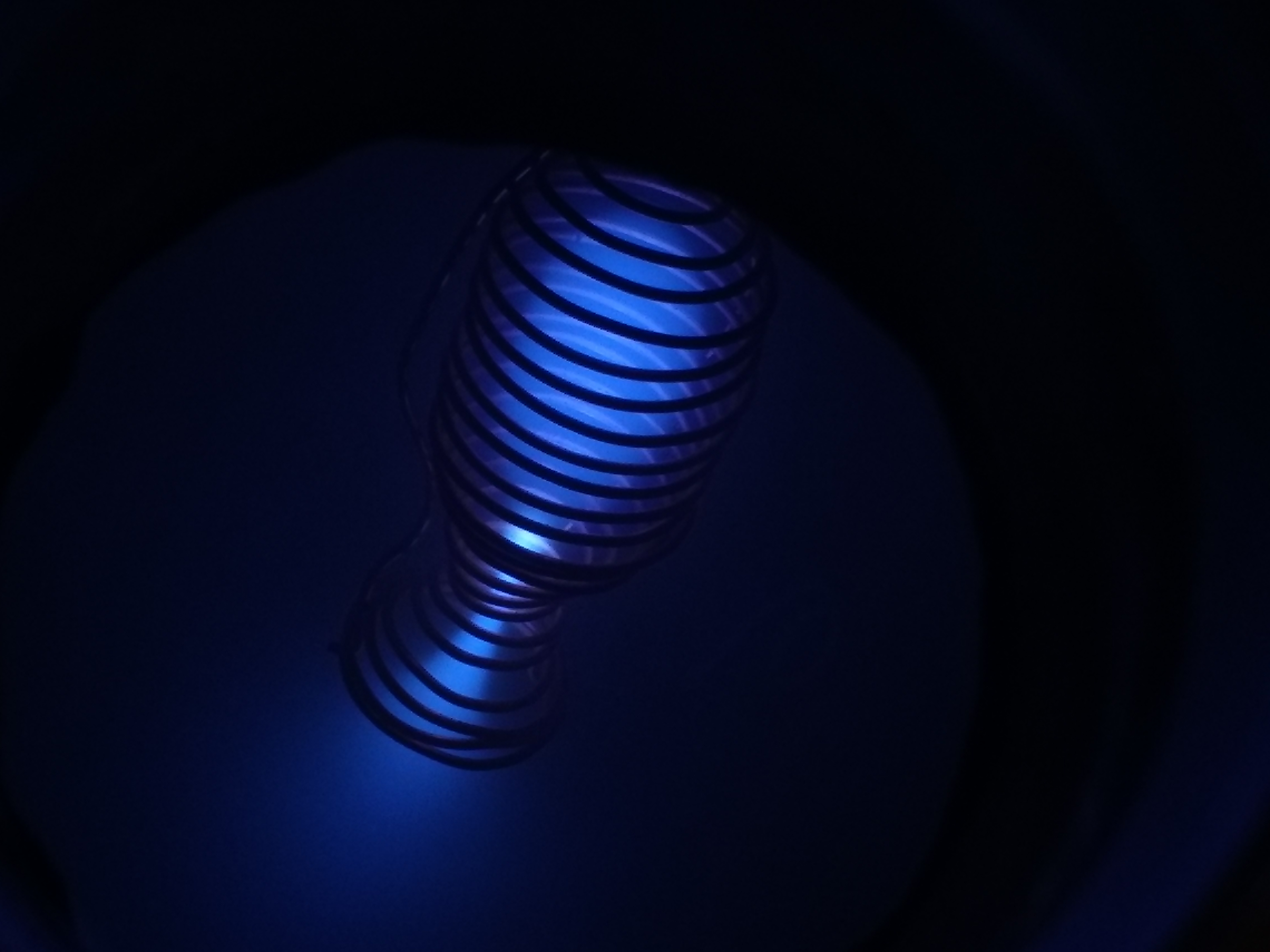 *Figure 9. Lower voltage applied than in the other images. The nozzle throat still is a white hot plasma.*  *Figure 10. GIF showing the transition from a leaky plasma to normal operation to molecular beam. GIF is playing in real time.* If you have any questions or suggestions, let me know in the comment section! **Further Reading** [de Leval Nozzle](https://en.wikipedia.org/wiki/De_Laval_nozzle) [Ion Thrusters](https://en.wikipedia.org/wiki/Ion_thruster) **Sources** Charged Ring: [https://physics.stackexchange.com/q/337905](https://physics.stackexchange.com/q/337905) [Liquid Rocket Engine Diagram](https://www.grc.nasa.gov/www/k-12/rocket/Images/lrockth.jpg) (NASA)
👍 hellfire-labs, terpgalaxy, technology-trail, terrylovejoy, carlgnash, r-bot, proteus-h, dunia, curie, liberosist, meerkat, roelandp, anwenbaumeister, hendrikdegrote, locikll, kushed, spiry-btc, pharesim, troopaloop, azman, karolgg, jagarmarten, nonationnoborder, majestic10110, fisherck, boreas, steemstem, lafona-miner, anarchyhasnogods, lemouth, justtryme90, mobbs, the-devil, foundation, rachelsmantra, nitesh9, kerriknox, gra, rockeynayak, rjbauer85, pearlumie, sci-guy, amavi, mystifact, kenadis, carloserp-2000, leczy, juanjdiaz89, jade56, tfcoates, shammi8448, leom1969, alexdory,