Electronics Component Basics: The Unijunction Transistor
steemstem·@proteus-h·
0.000 HBDElectronics Component Basics: The Unijunction Transistor
One of the simplest types of transistors is the now somewhat obsolete Unijunction Transistor, or UJT. Invented in 1953, the UJT acts a electrical switch. It can be used similar to a relay, but in an all solid-state package. This post will be somewhat short today, but I hope to cover the basics of UJTs in a concise manner. ## What does an UJT do? UJT's are three-pin devices. One pin, confusingly called the "emitter", controls whether or not electrical current can flow between the other two pins. Here's the schematic symbol for the UJT: 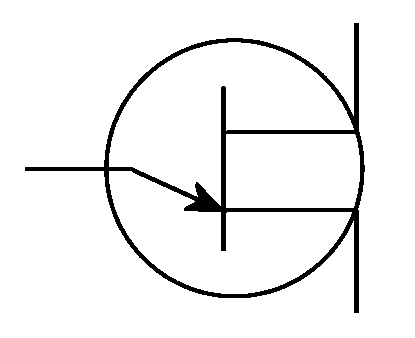 *If you see this in a circuit diagram, it means Unijunction Transistor.* *[Credit](https://commons.wikimedia.org/wiki/File:UJT_simbolo.png)* Simply put, the horizontal line controls the conductivity of the two vertical lines. In its natural state, the UJT acts as a high value resistor (several thousand ohms). If you try to connect it to a battery, only a tiny current will flow across the UJT. This is the "off" state, and it is the state that the UJT will return to in absence of any external actions. What makes the UJT useful is what happens when you use the third pin, the emitter. "Turning on" the emitter will let current easily flow across the other two pins, letting the UJT act like a switch. Apply a big enough (but still somewhat low) voltage between the emitter and either of the other pins (called base1 and base2) will "turn on" the UJT, allowing a very large current to flow across base1 and base2. 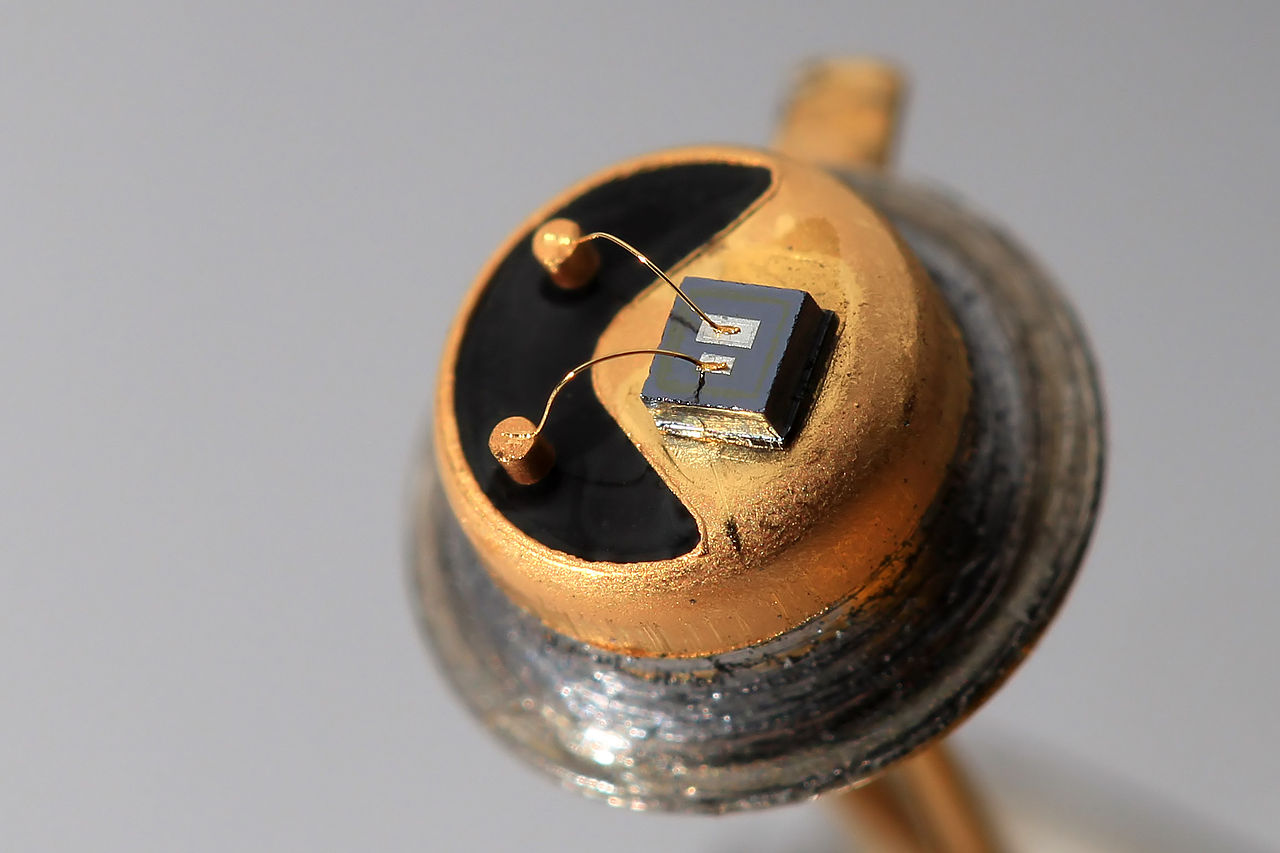 *Cut-open UJT. The big rectangular patch is the Emitter.* *[Credit](https://commons.wikimedia.org/wiki/File:Unijuction_transistor_KT117_(open).jpg)* The current through the emitter (the "switching pin") itself also has an interesting characteristic. As the voltage increases, current increases linearly (just like a resistor). But reach a certain peak voltage, and the current will suddenly begin to increase as the voltage *decreases*. This is known as "negative resistance", since it makes the emitter-base current path act like a "reverse resistor". I'll get back to this in a bit. ## Construction Like diodes, UJTs are created out of a single n-doped and p-doped semiconductor material. A UJT is essentially mostly n (negative) semiconductor with a small region of p (positive) semiconductor attached. The n semiconductor is a pretty bad conductor in general, hence why the UJT doesn't conduct current very well when "off". Applying a high voltage to the p-region "turns on" the n-region, allowing current to easily flow across the now conductive region. But it's really not that different from the diode. The path from the emitter to either of the bases is, after all, a p-n junction, and as such this path acts like a diode and only allows current to pass in one direction. 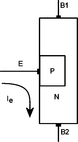 *Unijunction Transistor composition. The makeup of this device means that the ordering on the bases doesn't matter: You can use base1 as the higher voltage terminal just as well as base2. In this case, the emitter is at a higher voltage than base2, so current flows to base2 and turns on the UJT.* *[Credit](https://commons.wikimedia.org/wiki/File:UJT_struttura.png)* The underlying semiconductor is usually silicon, with different elements being used to form the n and p regions. ## Uses for UJTs Now to cover what we can actually use these devices for. The simplest way to use a UJT is just as an electrical switch. Say you want to turn on a circuit or part of a circuit using a signal from another circuit. You can use the UJT for this, just feed the (sufficiently large) signal from the UJT emitter to one of the bases and you can switch the transistor on and off. This method makes the UJT just like a solid-state [relay](https://steemit.com/steemstem/@proteus-h/electrical-component-basics-the-electromechanical-relay) but without the easy to break moving parts. The UJT can switch much faster than any relay, but may not be able to take as power/current through it before breaking. At its heart the UJT is just a switch. This makes it useful for things other than just turning on and off parts of a circuit (although in the end that's all it's really doing...) One example is to make an *oscillator*, which is just any circuit that can rapidly switch a signal on and off. Every radio transmitter (including the wifi transceiver in your computer) contains an oscillator to drive the electromagnetic waves being transmitted. Remember the "negative resistance" I mentioned earlier? This effect can be used to make an oscillator. Place a capacitor between the emitter and one the bases. Now, place a big resistor between the capacitor and a battery, and connect the battery across the UJT. Once the capacitor charges to the threshold voltage, it will rapidly be drained through the emitter of the UJT due to the negative resistance effect. Once the voltage gets to the "saddle voltage" (the low point of the negative resistance curve), the capacitor can recharge until it once again reaches the threshold voltage and the cycle repeats. This produces a sort-of triangle wave, with a frequency determined by the size of the charging resistor and the capacitance of the capacitor. Like any oscillator, it can be used to drive transformers, change voltages, quickly turn stuff on/off, or even radiate radio waves (at frequencies determined by the frequency of the wave and the waveform itself). 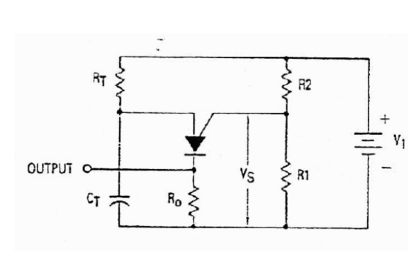 *Similar oscillator to the one described above, using a programmable UJT (a similar device to the standard UJT)* *[Credit](https://commons.wikimedia.org/wiki/File:Ejemplo..png)* __________________________________________________ Even though the standard (non-programmable) UJT itself is going the way of the vacuum tube rectifier (it's rarely used anymore, and the individual parts are getting harder and harder to find, now costing several dollars a piece), it serves as an interesting and less complicated introduction to transistors and solid-state switches. Hopefully you learned something new about them today. Let me know if you have any questions or comments, or if I made any errors. *Thanks for reading!* **Sources/Additional Reading:** [All About Circuits: The Unijunction Transistor](https://www.allaboutcircuits.com/textbook/semiconductors/chpt-7/unijunction-transistor-ujt/) [British Amateur Electronics Club: UJT](http://baec.tripod.com/DEC90/uni_tran.htm)
👍 proteus-h, tauseefkhan, kontora, team, veckinon, bachuslib, shaka, smasher, terrylovejoy, ribbitingscience, irelandscape, jarric, chunger, oliver391, choogirl, mcw, dmxmaster, zest, lunanightshade, gunsmithing, steemstem, lemouth, anarchyhasnogods, robotics101, justtryme90, mobbs, the-devil, lamouthe, foundation, rachelsmantra, nitesh9, kerriknox, gra, rjbauer85, mrs.agsexplorer, grandpere, timsaid, timothyb, jamhuery, kryzsec, alexander.alexis, ovij, somethingburger, kedi, amavi, dber, gentleshaid, carloserp-2000, kenadis, hadji, fredrikaa, leczy, dysfunctional, altherion, ertwro, churchboy, de-stem, pharesim, pangoli, deutsch-boost, steemstem-bot, chosunone, sese317j, dna-replication, curie, locikll, xanderslee, markangeltrueman, aboutyourbiz, howtostartablog, justdentist, spectrums, hendrikdegrote, keshawn, anwenbaumeister, musicayfarandula, zipporah, pacokam8, kushed, oscarcc89, tensor, wanderingdanish, nobyeni, lenin-mccarthy, steemulator, coloringiship, minatubo,