Creating Surface and Contours From Measurement Survey Data In AutoCAD Civil 3D
engineering·@whalhesa·
0.000 HBDCreating Surface and Contours From Measurement Survey Data In AutoCAD Civil 3D
***  *** Good afternoon all steemit friends. glad to meet you again and hopefully healthy always. After previously we share about how to input coordinate measurement survey data to AutoCAD Civil 3D, now I try to share about how to create surface and contour in AutoCAD Civil 3D. Before we start creating contours, we have to input data first as we discussed yesterday in the article: <a href="https://steemit.com/utopian-io/@whalhesa/import-data-survey-to-autocad-civil-3d" rel="noopener">Import Data Survey to AutoCAD Civil 3D</a> For the first step after the data in import is click menu Home> Surface> Create surface, As of the following picture: 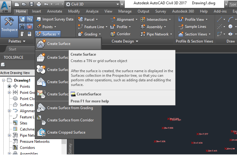 Next comes a new dialog box like the following picture: 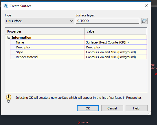 In this dialog box, we are required to choose what type Surface we will use later. Please select the TIN Surface option. Then in the menu properties, we will be asked to fill in the name of the surface following the style of the contours that we will display later. For this exercise please leave it in its default condition. Then click OK. Now we have finished creating the surface, Next, we will try to enter our survey measurement data into the surface that we created earlier. To enter survey data into the surface that we have created, friends can go to the top menu bar and select the menu modify - surface 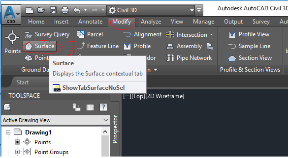 Then a new menu appears, select Add data> Point files or point group. in this example, we select Point Group. 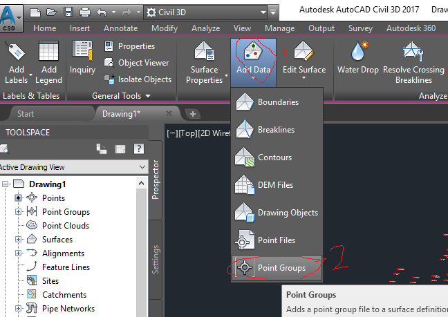 After the dialog box appears, select All point, then click apply and ok 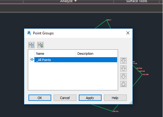 Will come out our surface and the contour image like the display below: 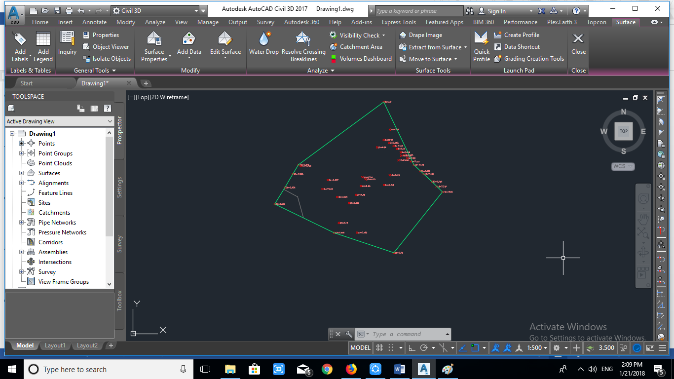 because at the beginning we did not specify the contour, interval than by default AutoCAD Civil 3D will generate default contour interval with 2 meters for its minor contour and 5 meters for its major contour. To change style of contour and contour interval, first we click surface in AutoCAD area, then on menu bar will exit surface properties, 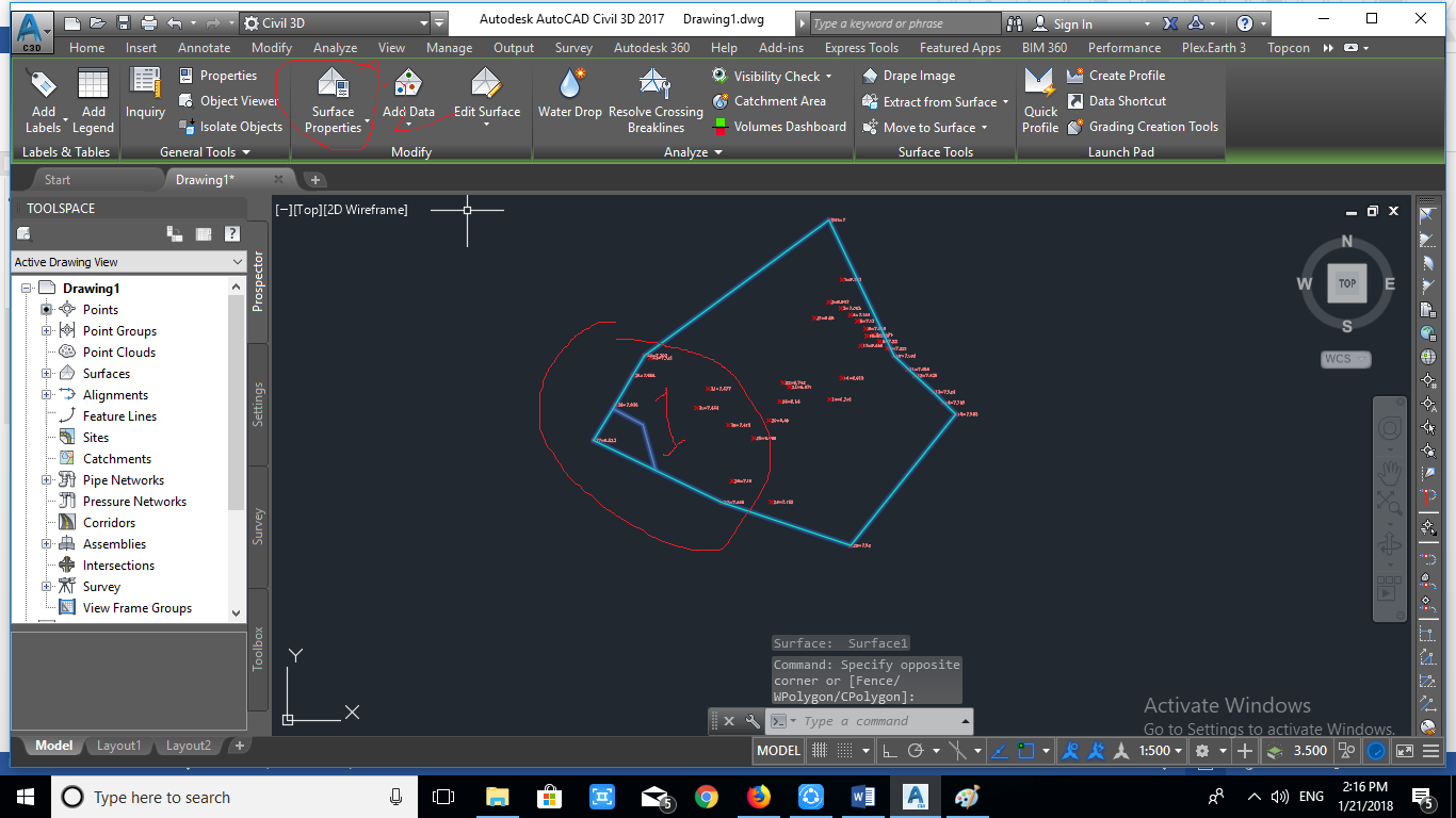 select the surface properties and will exit the new dialog box as follows. 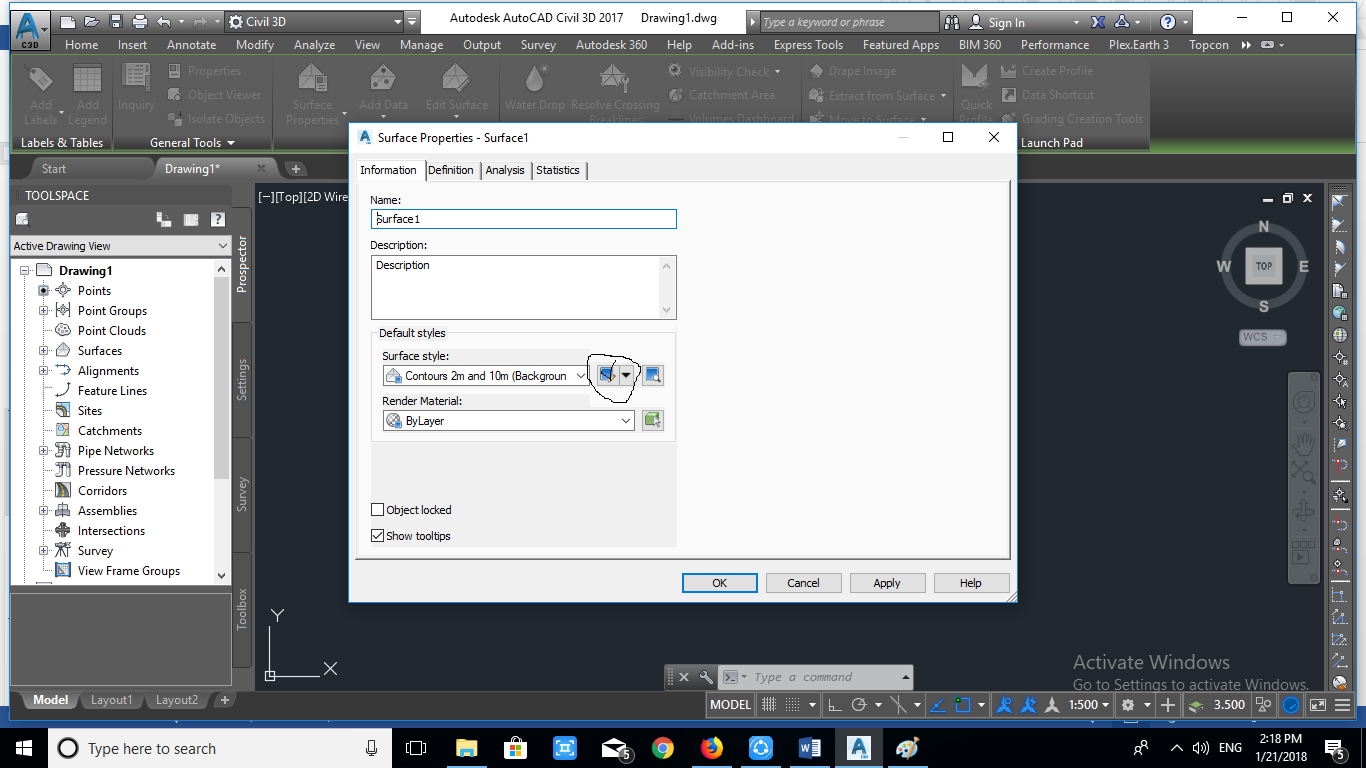 In the new dialog box select the Information menu then in the Surface Style click the right side icon until the following dialog box appears: 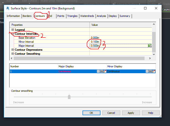 In the dialog box select on the menu Contour - Contour Interval. Then fill in accordance with the wishes of friends how the interval contours. For example in this exercise we will choose the minor contour of the interval is 0.1 meters and for the major contour the interval is 0.5 meters. Then click Ok. 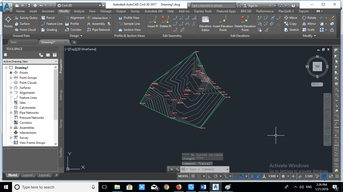 that's how to create surface and contour lines in AutoCAD Civil 3D, Hopefully useful.....!!! best regard @whalhesa *** https://steemitimages.com/0x0/https://steemitimages.com/DQmRKgYYp1TzWmvqtnfbMSLZQSgUXinUxqyHyd39HZ8j7gx/DQmRKgYYp1TzWmvqtnfbMSLZQSgUXinUxqyHyd39HZ8j7gx.gif